Introduction
Hi @everybody, I’m Ret2pwn in this series I’m going to talk about hardware hacking from zero knowledge to zero day. In part 1 we will look into basic definitions.
I’m not geek at IoT/Hardware Hacking, so if there any feedback contact me on twitter @Ret2_Pwn. I hope you all enjoy my series.
Prerequisites
Basic knowledege of reverse engineering, assembly. In case you are not familiar with them, I would recommend you to watch the following series.
Reverse Engineering
Assembly
Summary
In this blog post, I discussed what is the UART and how to find it on the circuit board to get a cute shell.
Hardware Tools
- Router
- Multimeter
- Logic Analyzer
- UART
Table of Contect
Definitions
You may face at least one of the following:
- UART
- JTAG
- SPI
- I2C
In this section, I’m going to define the UART interface, and in the up next blogposts, I will discuss the rest of them.
Universal Asynchronous Receiver-Transmitter (UART) Interface
What is UART?
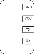
UART is so simple consists of 4 pins, used to transmit and receive to communicate through digital pin 0, digital pin 1. And there are two other pins, one for ground (GND) and one for VCC.
Note: UART communicates asynchronously. That means it doesn’t require a clock or synchronization of communication.
Here is a sample of How is UART interface looks like
How UART works?
Before diving into How UART works, I would recommend you to read this awesome post UART: A Hardware Communication Protocol Understanding Universal Asynchronous Receiver/Transmitter.
After reading that post I will simplify it by an example.
What if we have a conversation between two persons, One of them will talk and other one will listen to him, and then the listener will start talking and the other will listen. Right?
So now we have 4 pinouts in the UART interface. let’s break them aparts.
- Ground (GND).
- Voltage Common Collector (VCC).
- Transmit (TX).
- Receive (RX).
Fine, so what if we need to initial communication between two UARTs?
As the previous example we will need to do the following steps:
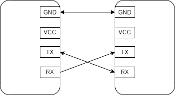
- Connect the TX of the first UART with the RX of the second UART.
- Connect the RX of the first UART with the TX of the second UART.
- Connect the GND of the first UART with the GND of the second UART.
| GND | GND |
| TX | RX |
| RX | TX |
See it is so simple. But wait we didn’t use the VCC pin? Yea I know the VCC pin is not important for us now.
How to find UART Interface?
As we see in the below-printed circuit board.
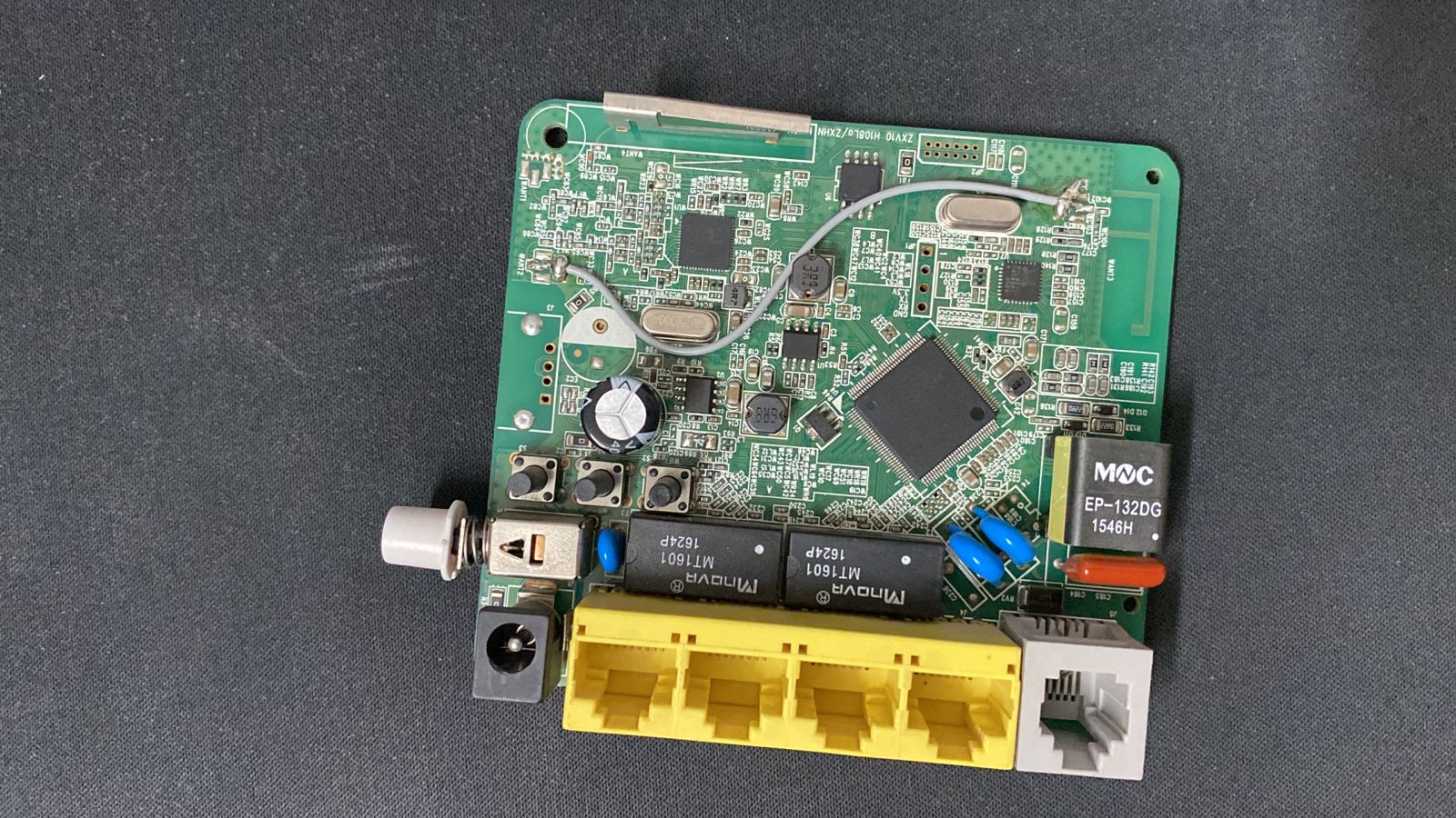
As I mentioned before UART has just 4 pinouts and as usual you will find them behind each other. So if we take a close shot, we will find the UART interface.
Questions
Is it normal to find the UART pins identified?
No, I’m just lucky.Is there just one UART interface in the circuit board?
No, you may find more than one.How should I know the RX, TX, VCC, and GND if it is not identified on the circuit board? Oh, nice one the answer below.
Multimeter
GND
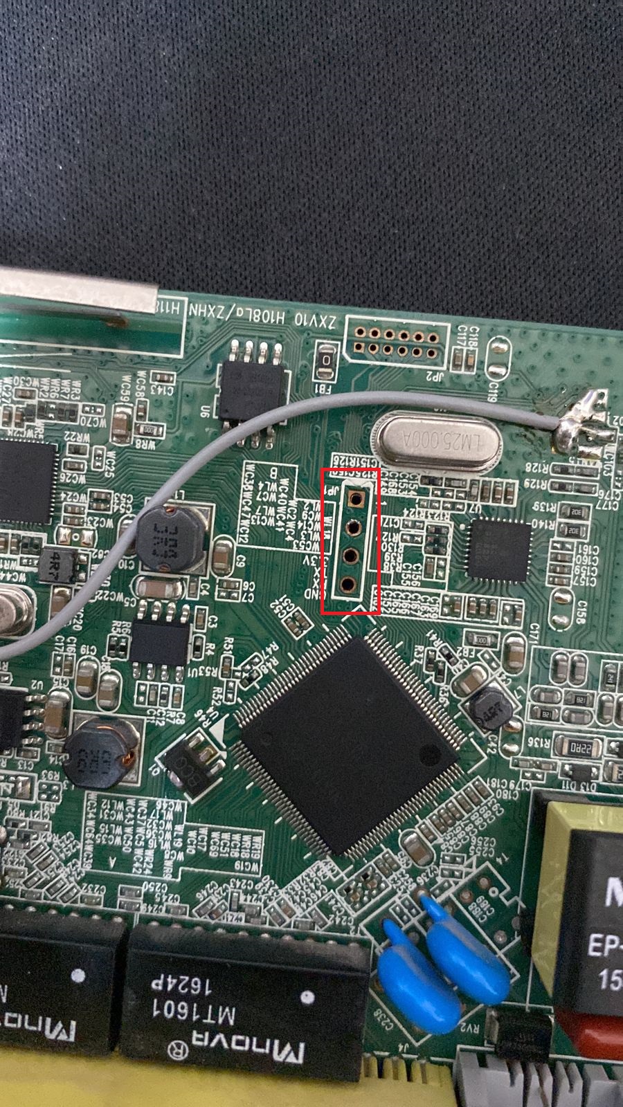
- Metal grid.
- USB Port.
- GND pin.
As you see below we have a metal grid.
So now everything is ready let’s start by rotating the multimeter switch to Conductivity mode, as shown in the image below.
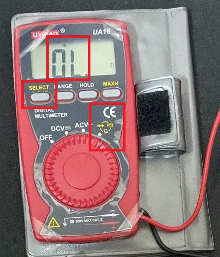
Then put one probe on the pin and the other probe on the metal grid, as in the image below.
If it beeps, that’s mean it is a GND pin. if not, move to other pins.
VCC
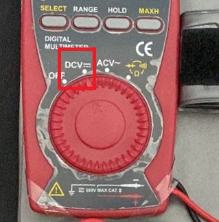
Let’s start by rotating the multimeter switch to DCV, as shown in the image below.
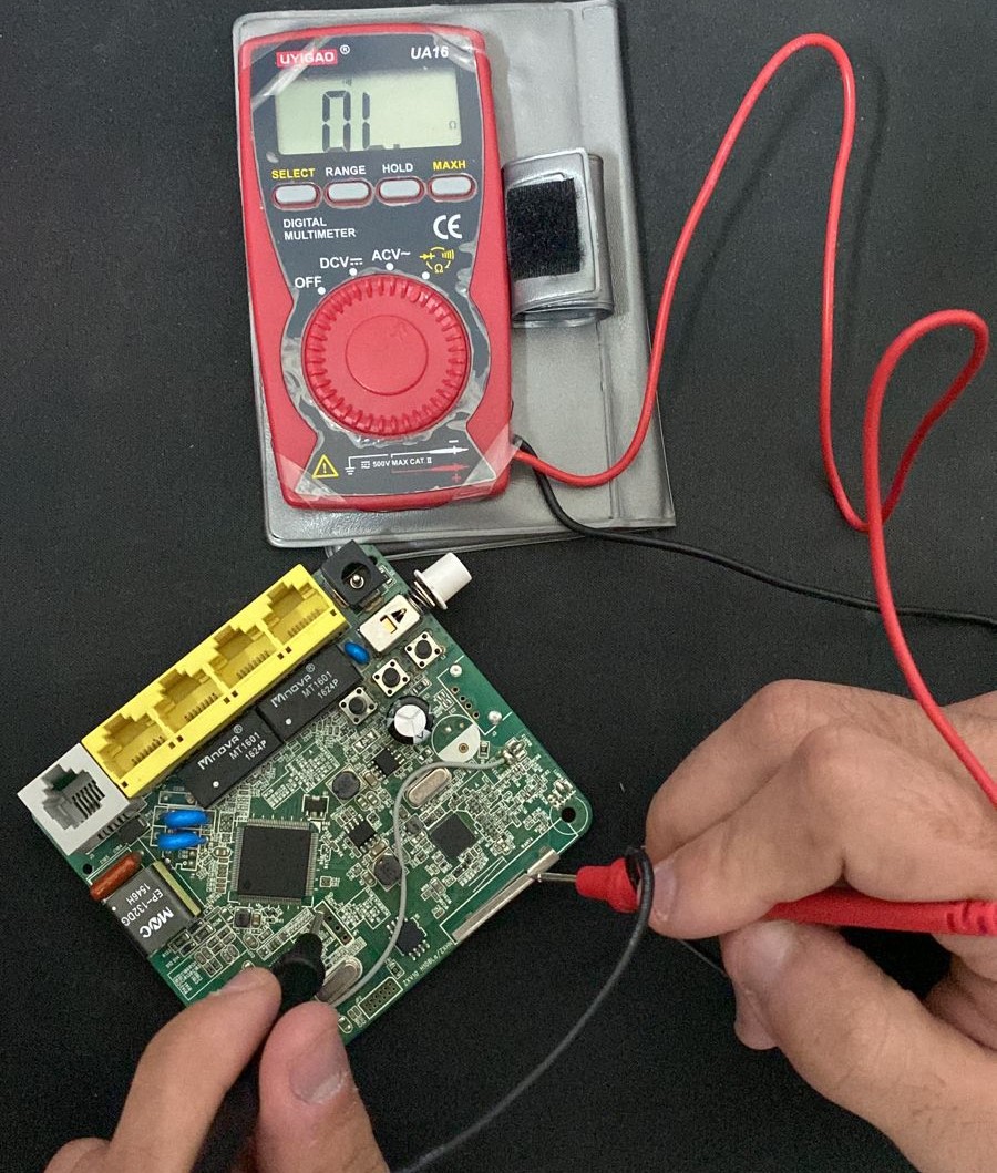
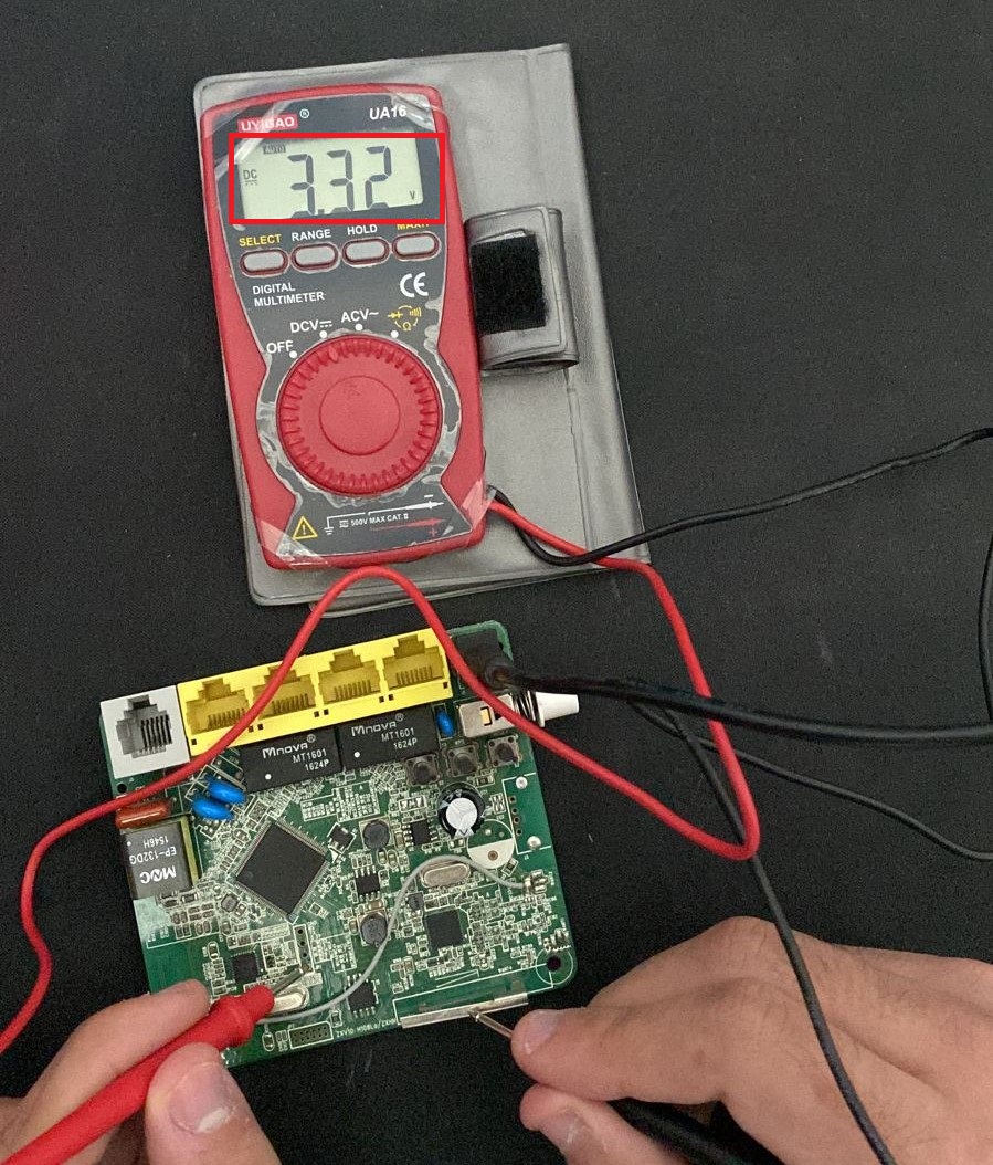
Then turn the power on, Then put the probe on the pin and the other probe on the metal grid. until we find one of the pins has 3.3V.
NOTE: Our board datasheet says VCC must be 3.3V.
TX
Here is the most confusing part because the voltage of the TX is not stable you may see it going up and down. Why that’s happening?
Because when it transmitted data each as logging the voltage will be low. So we can discover that easily in the booting processing.
So as usual let is put one of the probes on the pin and the other probe on the metal grid.
RX
Now we have 3 pins out of 4. by hard guess the last pin should be RX, right?
Start UART Communication
After discovering the UART pins, we would connect them.
So I will connect the RT with the TX, TX with the RX, and GND with the GND. as the below image.
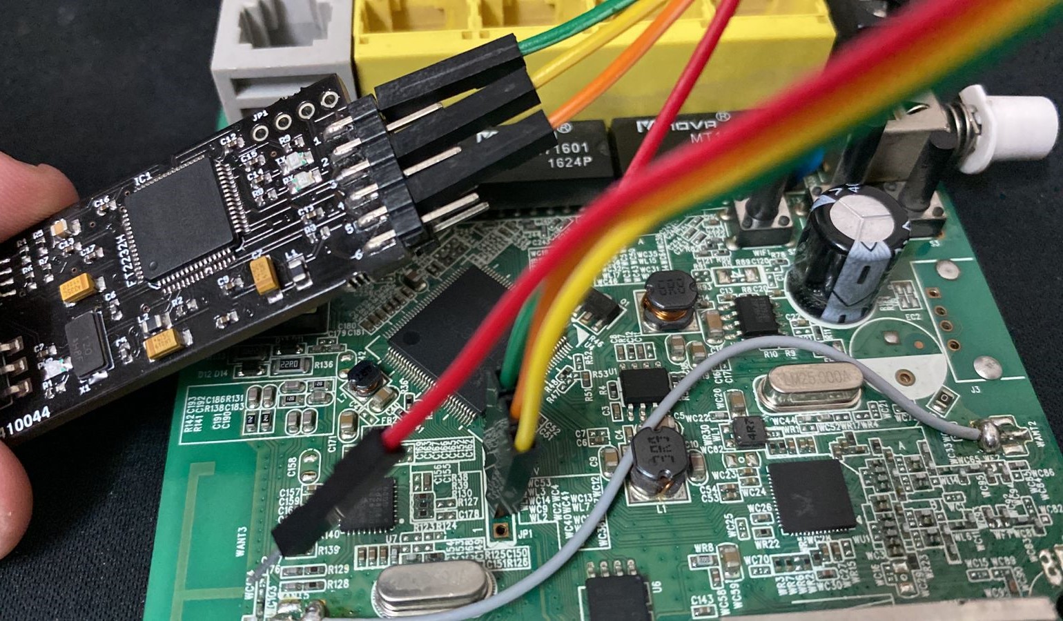
Then connect it to our laptop.
Okay so now we have done the hardest part, in here feel free you use any tool to communicate with the board.
Tools
- minicom
- screen
- PuTTY
- Tera Term
- Serial
- CoolTerm
- Terminator
I would like to use a screen to connect to the serial console, So I’m gonna select my correct host.tty, and correct read bit.
screen /dev/ttyUSB0 115200
When you connect to it, turn on the devices.
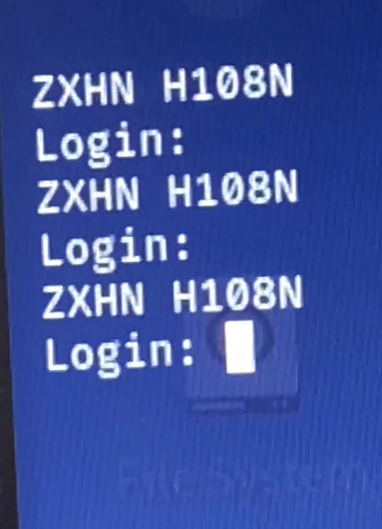
Easy, right?
Issues
You could face two issues.
- UART could be closed as there is solder in the hole.
- UART’s paths could be cut.
Solder UART
You may face UART closed by solder as in the below image.
IMAGE_HERE
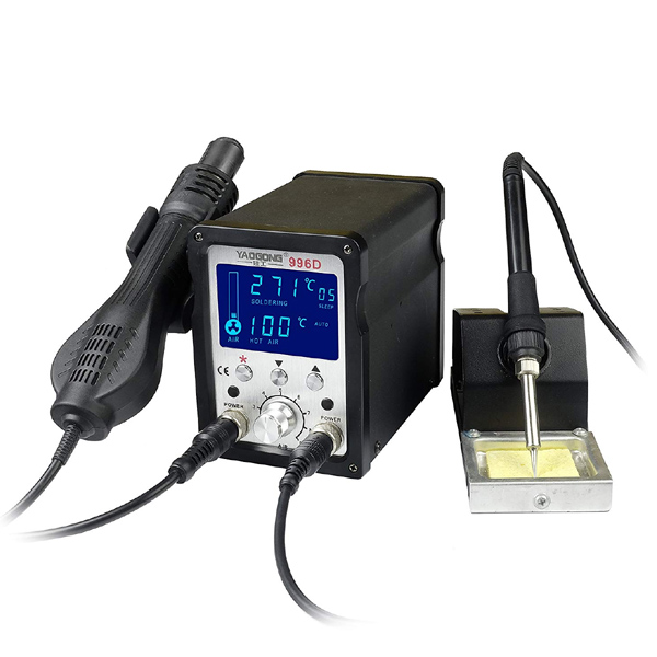
In this case, you will need to use a Hot Air Brushless to remove that solder out of the UART hole.
Hot Air Brushless
Broken UART
For broken UART you can see this part of Flashback Team.
Conclusion
I have Introduced a basic way to start communication with embedded devices (IoT) through the UART interface. Then I showed a real case on how to start UART communication. after that I showed two of the issue you may face in the UART interface.
Peace out!✌️